Ask ten engineers what "dynamic head" means and you will get at least two answers. In fluid mechanics, the term often refers to velocity head alone, the v2/2g component. In pump sizing, it almost always means total dynamic head, or TDH: the total equivalent height a liquid must be raised, including every loss it meets on the way. The dynamic head equation is the arithmetic that gathers static lift, pressure, velocity change and friction into one number you can compare against a pump curve.
Getting that number right matters more than most people expect. A pump chosen on vertical lift alone will fall short of its duty; a pump chosen with three layers of safety margin will run far to the left of its best efficiency point, wasting energy and wearing out bearings and seals early. Here is how the equation works in practice, and where the usual mistakes hide.
What the Dynamic Head Equation Actually Calculates
The equation is an energy balance written in units of head. A pump adds energy to the liquid; the liquid then spends that energy on four things: climbing from one level to another, overcoming any pressure already present in the discharge vessel, accelerating from suction pipe velocity to discharge pipe velocity, and fighting friction through pipe, fittings and equipment.
In its general form the equation reads:
TDH = static head + pressure head + velocity head + friction head
Every term has to be expressed as the same height of liquid column, usually feet or metres, before the terms can be added. That single rule explains most of the confusion around the equation, because pressure arrives in bar or psi, and velocity arrives in metres per second.
The Equation, Term by Term
Each part of the sum answers a different question about the system. The table below sets out what each term represents and how it is normally evaluated outside the classroom.
| Term |
What it represents |
How it is normally evaluated |
| Static head |
Vertical difference between the suction liquid surface and the discharge surface or discharge point |
Measured on site, not taken from an old drawing |
| Pressure head |
Pressure difference between suction and discharge vessels, converted into liquid column |
psi x 2.31 / SG for feet; pressure / (density x g) in metric units |
| Velocity head |
Kinetic energy difference when pipe or nozzle sizes change between suction and discharge |
(vd2 - vs2) / 2g; negligible when both diameters match |
| Friction head |
Losses along straight pipe at the design flow rate |
Darcy-Weisbach or Hazen-Williams, using real internal diameter and roughness |
| Minor losses |
Valves, elbows, strainers, check valves, entrance and exit effects |
Sum of K x v2/2g, or fitting tables from the same reference |
Table 1: Terms of the dynamic head equation and how each one is normally evaluated in the field.
The Full Working Form for a Pumped System
When suction and discharge references are pressures measured at the pump flanges, the equation is usually written like this:
TDH = (pd - ps) x 2.31 / SG + (vd2 - vs2) / 2g + (zd - zs) + hf
The factor 2.31 converts psi into feet of water, and SG corrects that figure for liquids heavier or lighter than water. In metric work the same structure holds, with pressure converted through density times gravity instead.
Many real systems simplify quickly. Pumping from an open tank to an open tank at the same elevation and pressure, the pressure and velocity terms drop away and the equation reduces to the version most people use daily: TDH = static head + friction loss. That is the definition worth remembering. Total dynamic head is the pressure needed while the water is actually flowing, covering both vertical rise and friction loss.
From the Equation to the System Curve
Only part of TDH changes as flow changes. Static head and pressure head stay fixed; friction rises with roughly the square of flow, so friction head is close to K x Q2. Plot the whole sum against flow and you have the system curve, a parabola sitting on top of a constant term.
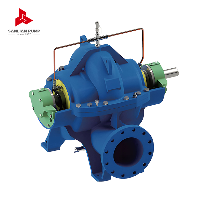
Place that curve over a pump's head-flow curve and the crossing point is the duty point. It should land near the best efficiency point, and it should leave enough NPSH margin on the suction side, because a pump that cavitates never delivers the head printed on its curve. Head, flow rate and motor power are bound together here, and it is worth understanding how these three quantities determine each other before a duty point is fixed. For large transfer duties with high flow and moderate head, a split-case machine usually sits closest to the ideal operating point, and the volute design keeps the hydraulic loads balanced across a wide flow range.
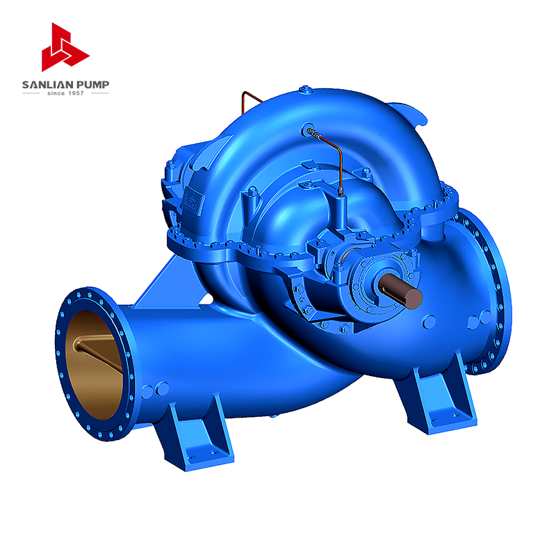 HS(V) Series Split Case Centrifugal PumpSingle-stage double-suction split volute centrifugal pump for high-flow, moderate-head transfer duties, with upper/lower split casing and balanced axial forces.View Product →
Where Field Calculations Usually Go Wrong
Years of project reviews leave a familiar list of errors. Most of them come from treating the equation as a formality rather than a description of the actual system.
- Counting only the vertical lift and quietly ignoring the friction that dominates long pipelines.
- Leaving suction-side losses out entirely, then wondering why the pump cavitates at high flow.
- Using nominal pipe size instead of real internal diameter, especially with old steel, lined or scaled pipe.
- Forgetting that nozzles, spray headers, heat exchangers and control valves all consume head.
- Carrying clean-water friction factors into slurry, pulp or viscous service.
- Adding safety margins to every term until the selected pump runs far left of its best efficiency point.
Slurries, Viscous Liquids and Hot Water
The equation itself does not change with the liquid, but its inputs do. A heavy slurry at SG 1.4 needs the same head in metres of slurry, yet considerably more power, because power follows specific gravity. Viscosity is harder to handle: it raises friction losses and reduces both head and efficiency, so correction factors or tested performance data are needed rather than a clean-water curve. Hot water adds a third concern, vapour pressure near the suction, which eats directly into the available NPSH margin.
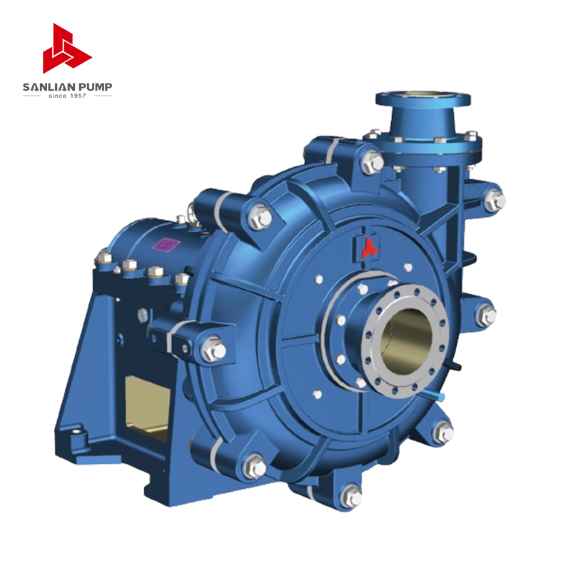
For abrasive duties the wear-resistant route is usually a horizontal slurry pump sized with a slightly generous head margin, since impeller wear and widening casing clearance move the duty point over time.
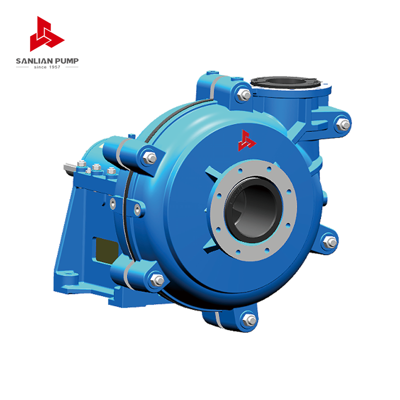 AH Series Horizontal Slurry Pump for Abrasive DutiesSingle-stage single-suction cantilever horizontal centrifugal slurry pump for abrasive, corrosive, high-concentration slurries; rubber-lined AHKR option handles fine particles.View Product →
From the Number to Equipment That Holds It
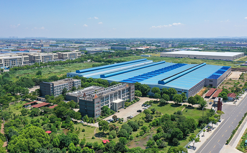
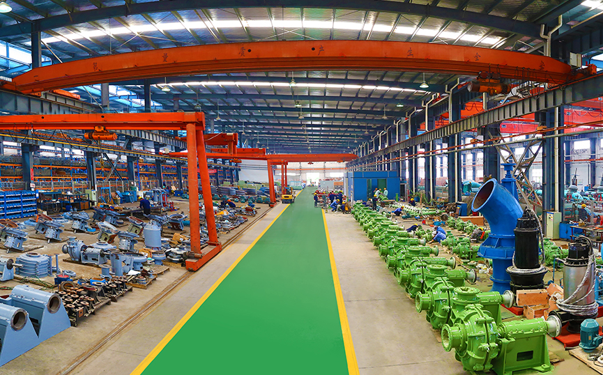
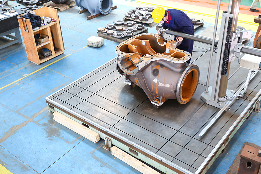
We have been building pumps since 1957, and the dynamic head equation has not changed in that time. What has changed is how much of it we control. Because we cast our own impellers and pump housings, the hydraulic passage can be matched to the calculated duty point instead of being chosen from whatever a supplier happens to stock. Our technical team works through the terms described above, then checks the result against site conditions, from chemical plants to mine drainage and municipal supply.
Where static head is large and flow is modest, such as boiler feed, high-rise water supply or dewatering from deep mine levels, a multistage centrifugal pump carries the duty in a smaller footprint than several single-stage units arranged in series.
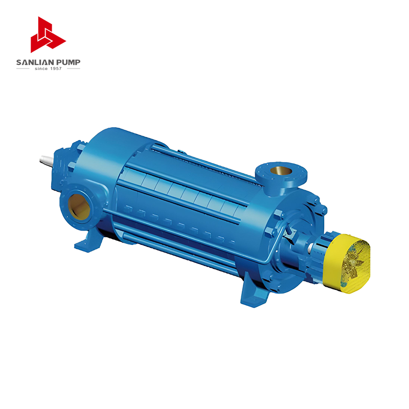 MD(S) Series Multi-Stage Centrifugal PumpHorizontal multi-stage centrifugal pump for high-head duties such as mine drainage and water supply, including MD wear-resistant and MDS double-suction first-stage variants.View Product →
Where the system is municipal or agricultural and total head is dominated by friction across a long pipeline, the choice usually falls to high-flow machinery, and the calculation is worth verifying against reference projects such as the Puyang South-to-North Water Diversion supporting water works, where measured duty points were compared with design figures after commissioning.
If you take one habit from all of this, let it be the order of work: define the flow, measure the static head, decide the pipe size, calculate friction and minor losses, sum everything, and only then open a pump curve.
- Fix the design flow rate for the case that matters most.
- Measure static head on site rather than reading it off an old drawing.
- Choose the pipe internal diameter and roughness values you will actually install.
- Add pressure, velocity and minor loss terms where they apply.
- Sum the terms, then compare the total with the pump curve at the duty flow.
- Re-check the result at roughly 25 percent either side of design flow.
None of these steps is difficult. Together they turn the dynamic head equation from a formula on a data sheet into a reliable prediction of what the pump will do on the day it starts running, and that is the version of the calculation that keeps projects out of trouble.



 English
 中文简体
中文简体 Français
 Español
 Português
 عربى
عربى


 皖公网安备34052302341647号