When a pump does not deliver the flow or pressure expected, the problem often starts with a head calculation that was too rough. At Sanlian Pump, we have worked with water utilities, chemical plants, mines, and steel mills since 1957, and one lesson repeats: the dynamic head formula is simple, but the details behind it decide whether the selected pump runs near its best efficiency point or struggles for years. This guide explains the formula, the components behind it, and how to use it in practical pump selection.
What Is Dynamic Head in a Pumping System?
Head is energy per unit weight of liquid, usually expressed in metres or feet. Static head is the elevation difference the liquid must overcome. Dynamic head is the part that changes with flow: friction through pipes, fittings, valves, and equipment, plus the velocity energy at the outlet. Some engineers use “dynamic head” narrowly for those flow-dependent losses. In pump sizing, the more useful quantity is total dynamic head (TDH), which adds static head and any pressure head the system requires.
TDH is not a fixed property of a pump. It is a property of the system at a given flow rate. Change the pipe size, add a control valve, or raise the discharge pressure, and the required head changes. That is why the formula should be applied at several flow points, not just one.
The Dynamic Head Formula at a Glance
A practical form of the total dynamic head formula is:
TDH = Hs + Hf + Hv + Hp
Where Hs is static head, Hf is friction head, Hv is velocity head, and Hp is pressure head. In low-pressure, open-tank systems, Hv and Hp are sometimes small enough to combine with a margin, but they should not be ignored without reason.
Components of the total dynamic head formula and their usual units in SI and US customary calculations.
| Component |
What it represents |
Typical unit |
| Hs |
Static elevation difference between suction and discharge liquid levels |
m or ft |
| Hf |
Friction loss in pipes, fittings, valves, and equipment |
m or ft |
| Hv |
Velocity head, calculated as v²/(2g) |
m or ft |
| Hp |
Pressure head required at the discharge point |
m or ft |
Use one unit system throughout. In SI, head is normally in metres of liquid; in US customary units, feet of liquid. Pressure converts to head with Hp = p/(rho g). A common shortcut is 1 bar ≈ 10.2 m of water and 1 psi ≈ 2.31 ft of water, but temperature and liquid density still matter.
How to Calculate Dynamic Head Step by Step
We usually start with a sketch of the system and a design flow rate. From there:
- Fix the design flow and pipe sizes. Flow velocity depends on the actual internal diameter, not the nominal pipe size.
- Calculate static head. For an open system, take the difference between the discharge liquid level and the suction liquid level.
- Estimate friction head. Include straight pipe, elbows, tees, valves, strainers, heat exchangers, and any other equipment in the path.
- Calculate velocity head. Use v²/(2g), where v is the flow velocity in the discharge pipe and g is gravitational acceleration.
- Add pressure head. If the pump discharges into a pressurised tank, header, or process, convert that pressure into metres or feet of the pumped liquid.
- Sum the components and check the result against the pump curve at the same flow rate.
As an example, suppose a system lifts water 30 m, has 6.5 m of calculated friction loss, discharges at 1.5 bar, and uses a 150 mm pipe at 120 m³/h. The velocity is about 1.9 m/s, so velocity head is roughly 0.18 m. Pressure head is about 15.3 m. TDH is therefore approximately 30 + 6.5 + 0.18 + 15.3 = 52 m. This is a screening calculation; final selection should use verified pipe schedules, fitting losses, liquid properties, and the pump curve.
Why the Formula Matters for Pump Selection
A pump selected for 40 m TDH but installed on a 52 m system will run left of its curve, often with reduced flow, higher vibration, and extra energy cost. A pump selected for 60 m on the same system may run far from its best efficiency point and waste power through throttling. The formula gives the duty point its proper place on the curve. Our article on pump head, flow rate, and motor power explains how those variables interact.
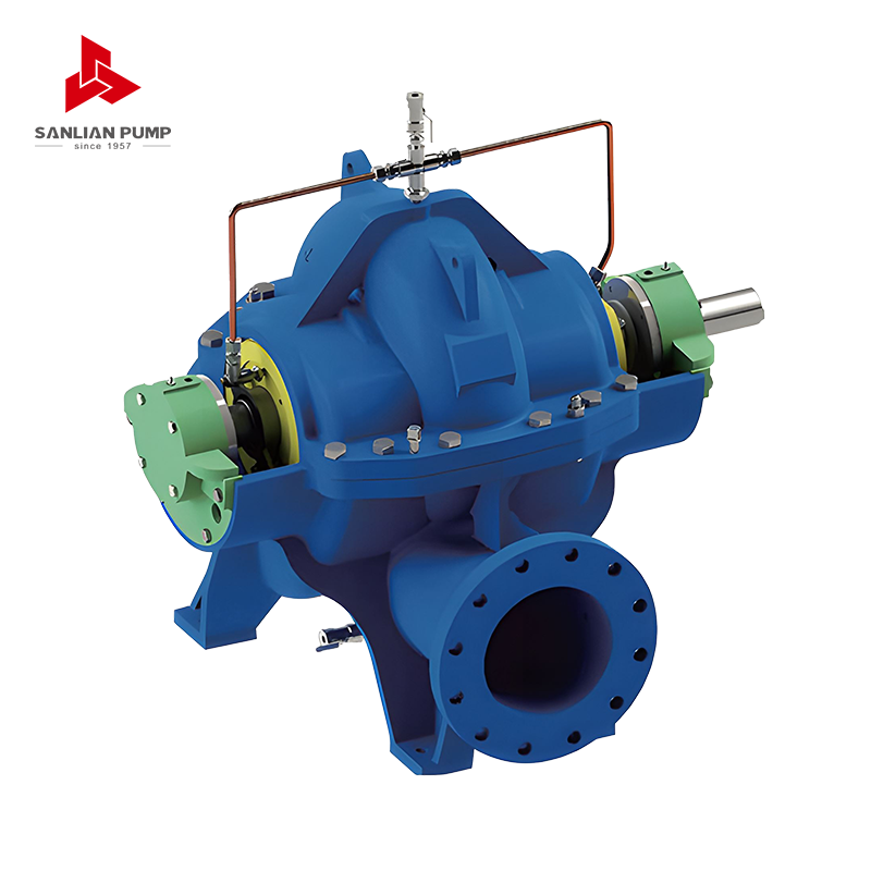
For high-flow, moderate-head duties such as municipal water supply and large circulation systems, a split case pump is often a good fit. Our HS/V series split volute centrifugal pump is designed for that kind of duty, with a layout that supports stable hydraulic performance and practical maintenance access.
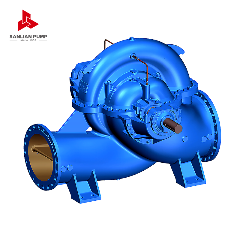 HS/V Series Split Case Centrifugal PumpSingle-stage double-suction pump for high-flow, moderate-head water supply and circulation duties, with split casing for maintenance access and hydraulic stability.View Product →
Common Mistakes and Practical Checks
- Using only vertical lift and forgetting friction. In long pipelines, friction can exceed static head.
- Ignoring fittings and valves. A few elbows and a partly closed valve can add several metres of head.
- Mixing pressure and head. Pressure depends on liquid density, so a water-based shortcut is not always valid for slurries, chemicals, or hot liquids.
- Using nominal pipe size instead of internal diameter. Pipe schedule and liner thickness change velocity and friction.
- Treating a slurry as clear water. Solids increase mixture density, friction, and wear, so the calculation needs slurry-specific correction.
- Forgetting suction-side conditions. TDH describes the system head; NPSH available is a separate check for cavitation risk.
For a real project view, see how these checks come together in the Nanjing Chemical Industrial Park central river pumping station, where flow, elevation, and system layout all shape the final duty point.
Matching the Formula to Different Pumping Duties
The same dynamic head formula applies across industries, but the weighting changes. In clean water supply, Hf and Hs usually dominate. In chemical service, pressure head and material compatibility may be more important. In mining, friction and wear assumptions must reflect the solids in the slurry.
Where the system needs high pressure in a compact footprint, a multistage pump can meet the duty by adding stages rather than relying on one large impeller. Our MD/S series multistage centrifugal pump is used for high-pressure transfer, boiler feed, and similar duties where the calculated TDH is well above what a single-stage end suction pump can handle efficiently.
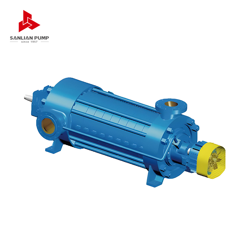 MD(S) Series Multistage Centrifugal PumpMultistage pump for high-pressure transfer and boiler feed duties, with D, MD, and MDS variants for clear water, mine drainage, and particle-laden service.View Product →
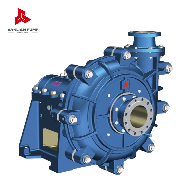
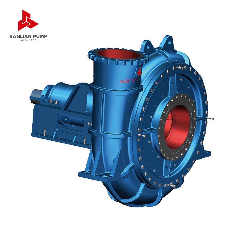
Slurries add another layer. The formula still starts with static, friction, velocity, and pressure head, but the friction term must reflect mixture density, particle size, and settling behaviour. Our AH series horizontal slurry pump is built for abrasive duties in mining, metallurgy, and mineral processing, where the head calculation and the wear life have to be considered together.
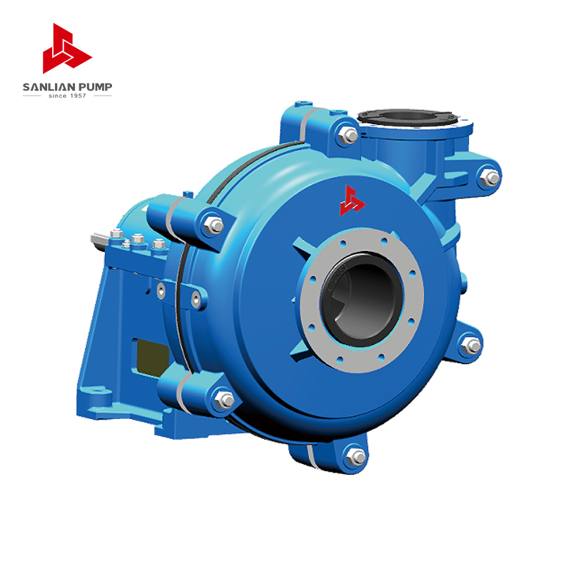 AH Series Horizontal Slurry PumpSingle-stage centrifugal slurry pump for abrasive, high-concentration solids in mining and metallurgy, with AHKR rubber-lined option for fine-particle duties.View Product →
If you are checking a duty point, start with the dynamic head formula, write down every component, and keep the units consistent. Then compare that system curve with the pump curve at the same flow. That simple discipline prevents most selection errors and gives operators a clearer basis for energy and maintenance decisions.



 English
 中文简体
 Français
 Español
 Português
 عربى


 皖公网安备34052302341647号