Ask three engineers to work out the head of the same installation and you will often get three different answers. Not because the physics is hard — the formula is short enough to fit on a sticky note — but because each person draws the system boundary in a different place. One measures to the pump centreline, another to the tank outlet, and a third quietly ignores the fittings because the drawing does not show them.
We have been building and sizing pumps since 1957, and the same handful of questions come up on almost every project. This guide works through them in the order we normally use: define the system, add up the components, check the result against a pump curve, and only then choose the machine.
What Pump Head Actually Measures
Head is energy per unit weight of liquid, expressed as a column height — metres in metric work, feet in imperial. Because it is normalised by weight, head stays the same whether you are moving water, caustic soda or a light slurry, while the pressure that the pipework actually feels changes with density. That is why a pump is selected on head and flow, and the mechanical design is checked against pressure afterwards.
The relationship between the two is simple: pressure equals density times gravity times head. For clean water, one bar corresponds to roughly 10.2 metres of column. For a dense slurry the same head produces noticeably more pressure at the casing, so a pressure gauge is never a direct substitute for a head calculation.
Head is also not the same as the reading on the discharge gauge. A gauge tells you the pressure at one point at one moment; total dynamic head describes the whole duty, including what happens on the suction side and what the fluid must overcome along the way.
The Total Dynamic Head Formula
For most installations the calculation reduces to four terms added together:
TDH = Hstatic + Hfriction + Hvelocity + Hpressure
Summary of the four head components and the physical effects each one represents.
| Component |
Symbol |
What it accounts for |
| Static head |
Hs |
Vertical difference between the suction and discharge liquid surfaces |
| Friction head |
Hf |
Pipe wall friction plus losses through valves, bends, filters and fittings |
| Velocity head |
Hv |
Kinetic energy given to the liquid, v² divided by 2g |
| Pressure head |
Hp |
Any pressure difference between the two ends of the system |
Two of these terms often vanish. In an open tank-to-tank transfer both surfaces are at atmospheric pressure, so pressure head is zero. At those same free surfaces the liquid velocity is negligible, so velocity head is usually counted only at the discharge point if the pipe ends in a nozzle or a spray header.
Static Head: The Straightforward Part
Static head is the vertical distance the liquid must be raised, measured between the two liquid surfaces rather than between pipe centrelines. In a drainage sump with a 3 m suction lift and a discharge tank 25 m above the pump, static head is 28 m — the suction lift is part of the total, not a separate bonus.
When the pump takes suction from a flooded header, the suction surface sits above the impeller and the static term may be small or even negative. That situation is good for cavitation margin but it changes the duty point, so it must be written into the calculation rather than assumed.
In a closed loop — a chilled water circuit, for example — the static head is only the elevation difference between the two gauge connections. If the loop is truly balanced, that difference is close to zero and the pump is effectively working against friction alone. Many overspecified closed-loop pumps come from forgetting this point.
Friction Losses: Where the Errors Usually Live
Friction head is the term that decides whether a selection is comfortable or marginal. The Darcy-Weisbach relationship remains the reference method: friction factor multiplied by length over diameter, multiplied by velocity head. For water networks, the Hazen-Williams form is quicker and is widely accepted for sizing checks, provided the roughness coefficient reflects the actual pipe — old steel and new plastic are not interchangeable.
Fittings are handled either by adding an equivalent length of straight pipe or by summing loss coefficients and multiplying by velocity head. In a plant room with many bends, reducers and valves, minor losses can easily add 20 to 40 per cent to the straight-pipe figure. Strainers, check valves and heat exchangers deserve their own allowance from the manufacturer's data.
Three practical adjustments keep the number honest. Add a fouling margin of 10 to 15 per cent for services that will scale or carry solids. Correct for viscosity when the liquid is thicker than water, because both friction and pump performance shift. And remember that a duty point calculated for a brand-new pipe will drift upward in flow as the pipe ages and roughness increases.
Pressure Head and Velocity Head
Pressure head matters whenever the system is not open to atmosphere: a pressurised vessel, a closed circuit with an expansion tank, a spray nozzle that needs 3 bar at the tip, or a filter that loads up over time. Convert the required pressure into metres of the pumped liquid and add it directly.
Velocity head is small in ordinary pipework. At 2 m/s in a water line it comes to about 0.2 m, which is noise compared with a 30 m static lift. At 5 m/s it rises to roughly 1.3 m, and in high-flow pipework or short discharge nozzles it stops being negligible. The honest approach is to include it every time and let the arithmetic show whether it matters.
A Worked Example
Take a municipal booster duty: 120 m³/h of clean water, drawn from a sump 4 m below the pump and delivered to a reservoir whose water surface is 28 m above it, through 180 m of DN150 steel pipe with a normal complement of bends and valves. Site levels for schemes of this kind, such as the Weinan municipal pumping water project, are usually surveyed well before the pumps are ordered, which makes the static term the easiest part of the calculation.
Velocity follows from flow and bore: 120 m³/h through DN150 gives about 1.9 m/s, so velocity head is 0.18 m. Friction, using a roughness coefficient suited to moderately aged steel, comes to roughly 4.4 m over the 180 m length, and the fittings add about 1.1 m. Adding everything together:
Worked example of total dynamic head for a 120 m³/h booster duty, with a 10 per cent design margin applied at the end.
| Item |
Value |
Unit |
| Suction lift |
4.0 |
m |
| Discharge elevation |
28.0 |
m |
| Static head |
32.0 |
m |
| Pipe friction |
4.4 |
m |
| Fitting losses |
1.1 |
m |
| Velocity head |
0.18 |
m |
| Total dynamic head |
37.7 |
m |
| With 10 per cent margin |
41.5 |
m |
Shaft power then follows from flow, head, density and efficiency. At 37.7 m and 75 per cent pump efficiency the duty needs about 16.4 kW at the shaft, so an 18.5 kW motor is the natural fit and a 22 kW frame gives headroom for the fouling margin. Checking the arithmetic this way before opening a catalogue saves a great deal of correspondence later.
From Total Dynamic Head to a Duty Point
Head on its own is only half of a selection. The system curve — static head plus a friction term that grows with the square of flow — must be plotted against the pump curve, and the intersection is the point the pump will actually run at. Because the relationship between head and flow is inverse, a pump trimmed for a higher head delivers less water, and one opened up for more flow delivers less pressure. The interaction between head, flow rate and motor power is worth reviewing before the duty is fixed, and our note on how pump head, flow rate and motor power determine selection covers that trade-off in more detail.
Two checks belong at this stage. Confirm that the efficiency at the duty point is close to the best efficiency point, since running far to the left or right shortens bearing and seal life. And confirm that available NPSH exceeds required NPSH by a working margin — typically 0.5 to 1 m — at the highest expected liquid temperature.
Matching the Calculation to the Right Pump
Once the duty point is known, the pump type usually follows from it. The differences between families are mostly about how much head each stage can generate and how the casing handles flow.
Low to moderate heads at modest flows
A single-stage end-suction pump is the workhorse for heads up to roughly 80 m in clean water, water supply and light industrial service. It is simple to install, easy to maintain, and a sensible default when the calculated head is dominated by static lift.
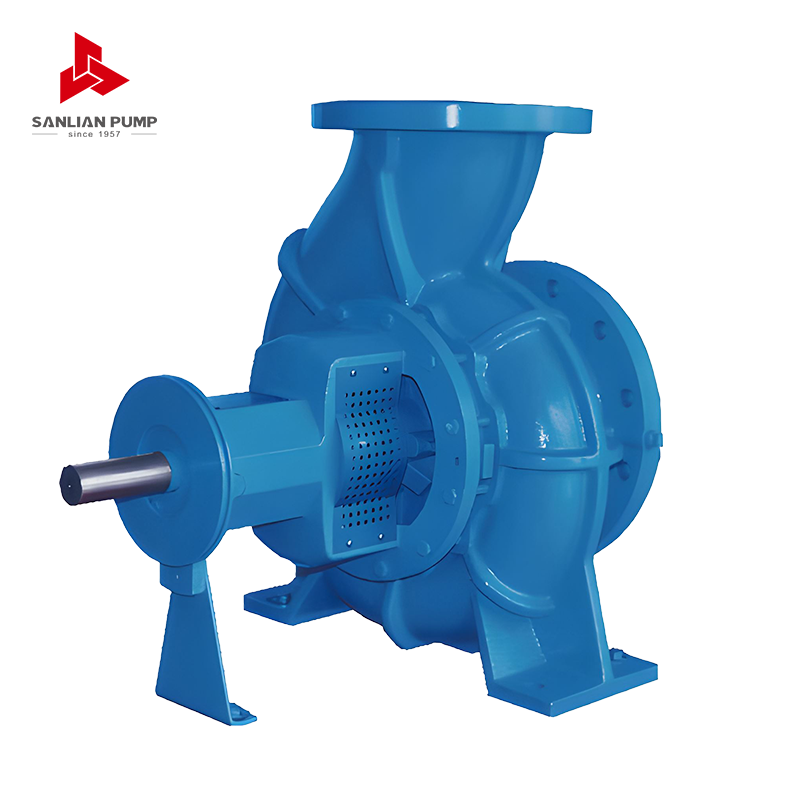 SPE Series Horizontal Single-Stage End-Suction Centrifugal PumpClean-water workhorse for heads up to 125 m, DN≤350 mm inlet and flows to 1600 m³/h; suited to supply, drainage and light industrial duties.View Product →
Large flows at moderate head
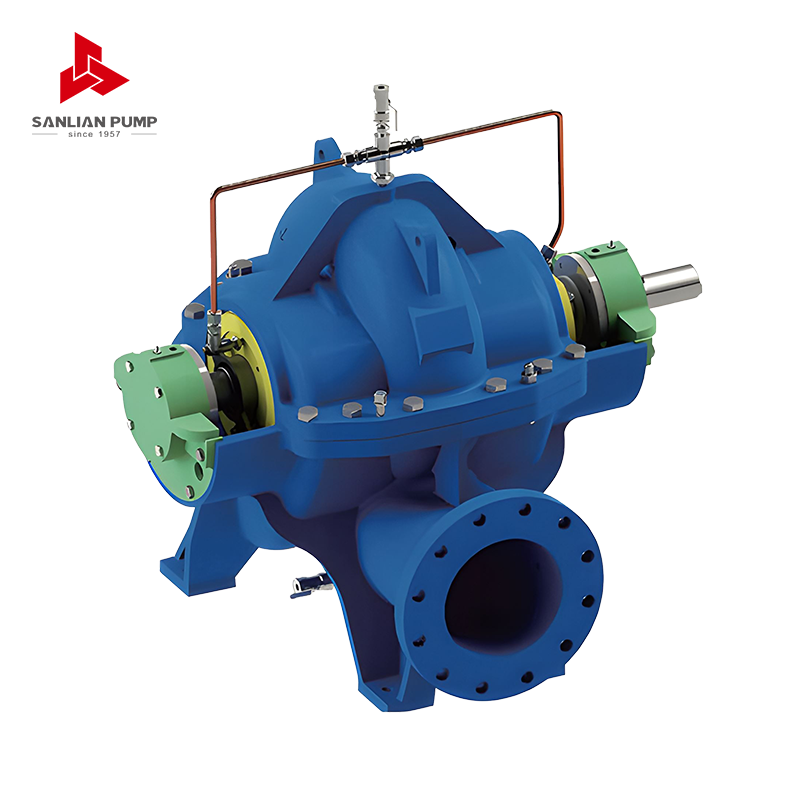
When the calculation produces several hundred cubic metres per hour against 30 to 60 m, a split case design handles the volume with a double suction impeller and low NPSH requirement. Municipal transmission and circulating water duties are typical.
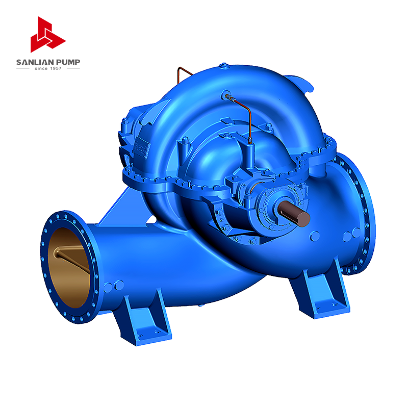 HS(V) Series Split Volute Double-Suction Centrifugal PumpHandles large flows up to 30,000 m³/h and heads to 200 m with a double-suction impeller; suited to waterworks, power plants and circulating water duties.View Product →
High head duties
Boiler feed, mine dewatering from depth and long rising mains often push total dynamic head past what a single stage can reach efficiently. A multistage pump adds head stage by stage, which keeps efficiency high while the casing pressure rating does the rest.
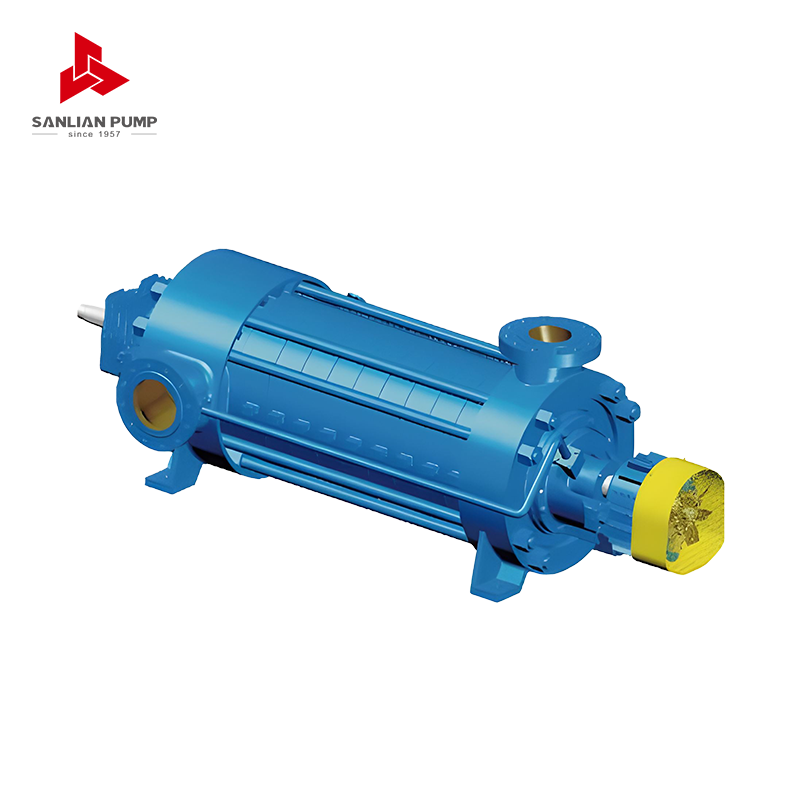 MD(S) Series Horizontal Multistage Centrifugal PumpAdds head stage by stage for mine drainage, with flow to 1250 m³/h, head to 1000 m and wear-resistant MD/MDS variants for 1.5% solids.View Product →
Getting the Number Right the First Time
Before a calculation leaves the desk, sketch the system and mark every liquid surface, every gauge point and every item that adds resistance. Note the fluid properties, not just the flow rate. Write the margin down as a number rather than leaving it in someone's head, and revisit the head once the plant is commissioned, because measured gauge readings on site are the only real proof that the sums were right.
Most selection problems we see are not caused by difficult hydraulics. They come from a missing fitting allowance, a static head measured to the wrong reference, or a closed loop treated as though it had to lift water it never lifts. Work through the four components patiently and the pump head calculation becomes what it should be: a short, reliable piece of arithmetic that tells you exactly what the machine has to do.




 English
 中文简体
 Français
 Español
 Português
 عربى


 皖公网安备34052302341647号