If you have ever stood beside a pump skid with a clipboard and a set of drawings, you know that “head” is one of those words that sounds simple until it is time to calculate it. The pump head formula is really a practical language for describing the energy a pump must add to move a liquid from one point to another. It helps you compare a system requirement with a pump curve before you commit to a selection.
In everyday pump work, total head is expressed in meters or feet. It is not the same as pressure, although pressure is part of the story. A working form of the formula is H = Hs + Hf + Hv + Hp, where static, friction, velocity, and pressure effects are added in consistent units. The relationship among pump head, flow rate, and motor power is what turns that number into a dependable duty point.
The Basic Pump Head Formula Without the Fog
Head represents energy per unit weight of liquid. In a simplified Bernoulli balance, the required pump head is the difference in pressure energy, velocity energy, and elevation between the suction and discharge sides, plus the losses along the way. For selection work, engineers usually group these terms into static head, friction head, velocity head, and pressure head.
Units are the first trap. If flow is in cubic meters per hour and head is in meters, keep density and gravity consistent when you calculate power. For water, pressure converts to head as head in meters equals pressure in bar multiplied by about 10.2, divided by specific gravity. In imperial units, head in feet equals pressure in psi multiplied by about 2.31, divided by specific gravity. For a fluid heavier than water, the same pressure produces less head, so do not skip the specific gravity correction.
Total Dynamic Head, Component by Component
Static head
Static head is the vertical difference between the liquid surfaces, plus any pressure difference that acts across the system. In an open tank transfer, it may be mostly lift. In a closed loop, elevation may cancel, but the pressure held by an expansion tank or process vessel still matters. Always define the start and end points clearly before adding numbers.
Friction and velocity head
Friction head comes from pipe walls, fittings, valves, strainers, and heat exchangers. Use equivalent lengths for fittings, and check whether the fluid is viscous or carries solids. Velocity head is the energy tied to flow speed, commonly calculated as velocity squared divided by twice gravitational acceleration. It is often small, but it is not always negligible in short, high-flow systems.
Table 1. Typical components used when calculating total dynamic head.
| Component |
What it represents |
Typical input |
| Static head |
Elevation and pressure difference between endpoints |
Tank levels, vessel pressure |
| Friction head |
Losses in pipe, fittings, valves, and equipment |
Flow, pipe length, diameter, roughness |
| Velocity head |
Kinetic energy of the moving liquid |
Flow rate and pipe area |
| Pressure head |
Pressure energy converted to equivalent liquid height |
Pressure, density, specific gravity |
When the Formula Points to High Head
Some systems ask for a modest flow at a high total head: boiler feed, deep-well transfer, high-rise water supply, or a long rising main. In those cases, a multistage pump may fit the duty better than a single-stage machine because the head is built up across several impellers. At Sanlian Pump, we have seen many projects where the first useful step is not choosing a model but separating the static lift from the friction and pressure terms.
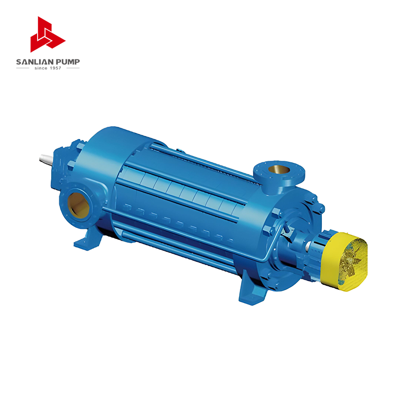 MD(S) Series Multistage Centrifugal PumpFor high-head duties such as mine drainage and water supply, this horizontal multistage series offers flow to 1,250 m³/h and head to 1,000 m.View Product →
A calculated head is still only half of the selection. Check the pump curve, efficiency, shaft power, and net positive suction head available. A pump can meet the head formula and still be a poor choice if it runs far from its best efficiency area or if suction conditions are marginal.
A Worked Example You Can Follow
Imagine a water transfer duty of 80 m3/h. The destination water surface is 32 m above the source surface. The discharge tank holds 0.5 bar, which is about 5.1 m of water head. Pipe and fitting losses are estimated at 8 m, and velocity head is 0.5 m. The total dynamic head is 32 + 5.1 + 8 + 0.5 = 45.6 m.
- Convert pressure to head: 0.5 bar × 10.2 = 5.1 m for water.
- Add static lift, pressure head, friction, and velocity head in the same units.
- Calculate hydraulic power: 80 × 45.6 ÷ 367 = about 9.9 kW.
- Divide by pump efficiency. At 65 percent, shaft power is about 15.3 kW.
- Add a sensible motor margin after checking the actual operating range.
This is a compact example, but it reflects the real work: gather the system facts, convert units carefully, and keep assumptions visible. That way, a colleague can review the calculation instead of guessing where the numbers came from.
Matching the Calculated Head to a Pump Curve
Total dynamic head describes the system. The pump curve describes the machine. The duty point is where the two meet. If the calculated head is far from the curve at the design flow, do not force the selection with a larger motor alone. Recheck pipe size, impeller trim, control strategy, and whether the design flow is truly the normal operating flow or only a short-term peak.
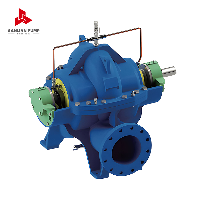
For large water supply and circulation duties, a split case pump can be a practical match because it handles substantial flow while keeping maintenance access straightforward. Our experience on the Puyang South-to-North water diversion supporting water works reflects the same principle: the head calculation must be tied to the real operating range, not just a single point on a drawing.
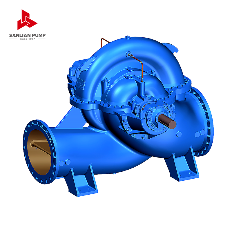 HS(V) Series Split Volute Centrifugal PumpSingle-stage double-suction pump for large water supply and circulation duties, with flow up to 30,000 m³/h and head up to 200 m.View Product →
Once the duty point is clear, review efficiency at the normal flow, not only at the rated flow. A pump that looks good at one point may use more energy through most of the year.
Common Mistakes That Distort the Result
- Mixing pressure and head without converting units or checking specific gravity.
- Using pipe length alone and forgetting fittings, valves, and equipment losses.
- Ignoring suction lift, suction pressure, or the net positive suction head available.
- Applying one large safety factor to every term instead of checking each assumption.
- Calculating only the peak flow and ignoring the normal operating range.
- Treating a slurry or viscous fluid as if it were clean water.
From Formula to a Confident Pump Selection
At Sanlian Pump, we have worked with fluid transfer systems since 1957, and the most reliable selections still begin with a clear system description. Share the flow range, fluid properties, temperature, suction conditions, pipe layout, control method, and expected operating hours. Our technical team can then cross-check the pump head formula against the pump curve and the real installation.
That approach is not about making the calculation complicated. It is about making it honest. A good head calculation gives the pump a fair chance to run efficiently, quietly, and with fewer surprises at commissioning.
The pump head formula is a compact way to describe a whole system: lift, pressure, friction, and velocity. Keep the units consistent, separate each component, and compare the result with the pump curve at the flows you will actually use. When the numbers are clear, the selection becomes much more than a catalog choice. It becomes a practical decision you can stand behind.





 English
 中文简体
 Français
 Español
 Português
 عربى


 皖公网安备34052302341647号