The efficiency of a pump is the ratio of hydraulic power delivered to the fluid to the mechanical power applied at the pump shaft. That simple relationship, expressed in the efficiency of pump formula, tells you immediately whether a pumping system is running near its designed performance or silently wasting energy. From water-supply networks to mineral processing plants, no other calculation has a more direct effect on operating cost.
The Pump Efficiency Formula
The standard pump efficiency formula is:
η = Phydraulic / Pshaft
where hydraulic power is the useful energy transferred to the fluid:
Phydraulic = ρ × g × Q × H
In this equation, η is total pump efficiency (0 to 1, or %), ρ is the fluid density in kg/m³, g is the gravitational acceleration (9.81 m/s²), Q is the flow rate in m³/s, H is the total head in metres, Phydraulic is the water horsepower equivalent in watts, and Pshaft is the shaft power in watts.
The overall efficiency also represents the combined effect of three internal loss groups:
- Hydraulic efficiency – friction and turbulence losses inside the casing, impeller, and volute.
- Volumetric efficiency – leakage losses through wear rings, balancing holes, and other clearances.
- Mechanical efficiency – bearing, seal, and stuffing-box losses.
Manufacturers talk about all three during design, but for the end user the total efficiency is the number that matters. Put another way:
ηtotal = ηhydraulic × ηvolumetric × ηmechanical
To understand how head, flow rate, and motor power determine the pump performance, start by measuring these variables on an actual pump.
Table 1. Variables in the pump efficiency formula and their common field units.
| Symbol |
Meaning |
Unit |
| η |
Total pump efficiency |
% or dimensionless |
| ρ |
Fluid density |
kg/m³ |
| g |
Gravitational acceleration |
m/s² |
| Q |
Flow rate |
m³/s |
| H |
Total head |
m |
| Phy |
Hydraulic power |
W or kW |
| Psh |
Shaft power |
W or kW |
Calculating Pump Efficiency with Common Field Units
In the field, flow is usually expressed in m³/h, head in metres, and shaft power in kW. Substitute these units into the efficiency of pump formula and the result is:
η = (ρ × g × Q × H) / (3.6 × 10&sup6; × Pinput)
where Q is now in m³/h, H in m, Pinput in kW, and ρ in kg/m³. The 3.6 × 10&sup6; constant converts m³/h to m³/s and kW to W in one step.
Here is a typical example. A water pump moves 180 m³/h at a total head of 60 m, and the measured shaft power is 45 kW. For clean cold water, ρ = 1000 kg/m³:
Phydraulic = (1000 × 9.81 × 180 × 60) / 3.6 × 10&sup6; = 29.4 kW
η = 29.4 / 45 = 0.654, or 65.4%
If the 45 kW is an electrical input reading rather than a shaft measurement, include motor efficiency in the calculation:
ηsystem = ηpump × ηmotor
For example, a motor with 92% efficiency would make the overall wire-to-water efficiency 0.654 × 0.92 = 0.60, or 60%.
Why the Efficiency Formula Matters for Operating Costs
The result of the pump efficiency formula is not a number to file away; it is a direct measure of cost. The difference between 65% and 75% efficiency on a 45 kW pump is real money.
Assume the pump runs 8000 hours per year and electricity costs $0.10 per kWh. To deliver the same hydraulic power at 65% efficiency, the shaft power is 45 kW. At 75% efficiency, the required shaft power falls to:
45 × (65 / 75) = 39 kW
The saving is 6 kW, or 48,000 kWh per year. At $0.10 per kWh, that is $4,800 per pump per year. A plant with 20 pumps can save close to $96,000 annually just by maintaining efficiency near the original design value.
This is why operators in high-wear industries pay close attention to the formula. For example, pumps in hard rock mining are periodically tested to identify when wear has moved their operating point away from the best efficiency point.
Main Factors That Reduce Pump Efficiency
Every pump has a best efficiency point (BEP), the flow and head combination where losses are smallest. The formula is simple, but in practice efficiency is influenced by several external and internal conditions:
- Off-BEP operation: Running too far left or right on the curve increases recirculation and turbulence. Efficiency can drop 10 points or more.
- Fluid viscosity: Higher viscosity increases friction losses and reduces Reynolds number; the hydraulic efficiency curve shifts down.
- Wear ring and impeller clearance: Internal leakage rises as clearances enlarge. In abrasive service, a few millimetres of wear can mean several points of lost efficiency.
- Cavitation: If NPSH available is too low, vapour bubbles collapse on the impeller and reduce head and efficiency while damaging the metal.
- Surface roughness and corrosion: Rough or pitted impellers increase friction losses and encourage material buildup.
Most of these factors can be identified through a combination of pressure gauges, flow meters, and motor power readings. Once you have these values, the efficiency of pump formula tells you how much margin you have lost.
Match the Pump to the Real Duty Point
In our experience, the most common cause of low efficiency is not an ageing pump but an oversized selection. Many pumps are specified for a maximum head that never occurs in normal operation. The result is a pump running far to the right on the curve at low efficiency and with high radial load.
For clean water duties, an end suction centrifugal pump with a selectable impeller diameter lets the engineer trim the rotor to match actual conditions. This keeps the operating point close to BEP over the life of the installation and reduces energy use without adding complexity.
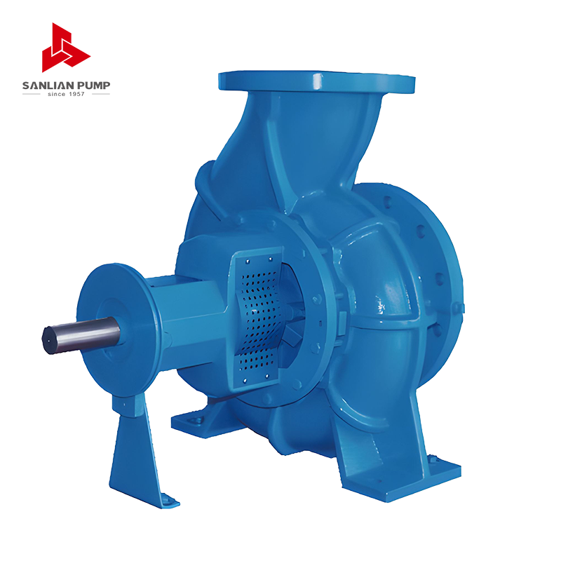 SPE Series Horizontal End-Suction Centrifugal Pump for Clean WaterThis horizontal single-stage end-suction pump allows impeller trimming to match actual operating conditions, helping keep the duty point near BEP and reducing energy consumption over the installation's life.View Product →
Use the Right Pump Type for Large Flow Rates
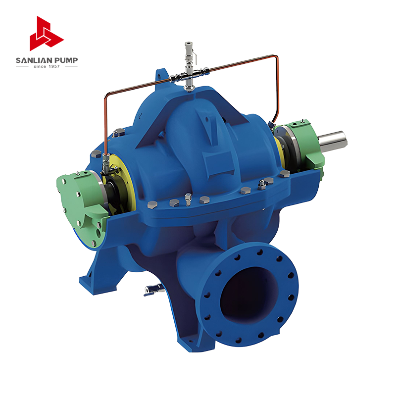
For large flows and moderate heads, the geometry of the impeller has a major effect on efficiency. Double-suction split case pumps reduce the entrance velocity at the impeller eye and balance axial thrust, which cuts hydraulic losses and bearing friction at the same time. This makes them a common choice for municipal water supply and industrial transfer systems that operate many hours per day.
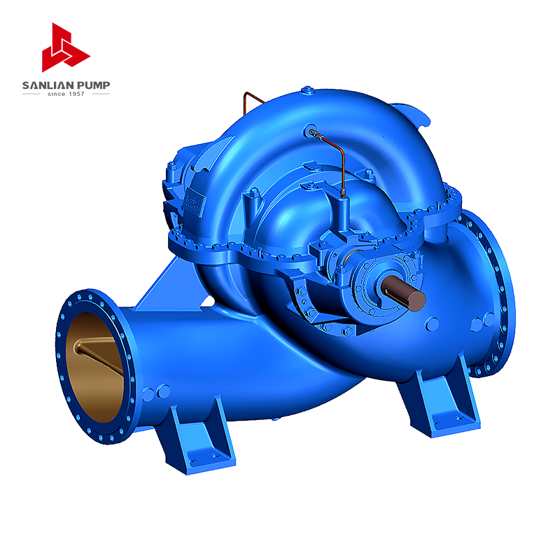 HS (V) Series Split Volute Double-Suction Centrifugal PumpThis new-generation single-stage double-suction pump features a split-case design with balanced axial thrust, dual volute casing, and anti-cavitation inlet guide plates, making it efficient for large-flow, moderate-head municipal and industrial duties.View Product →
Protect Efficiency in Abrasive and Corrosive Fluids
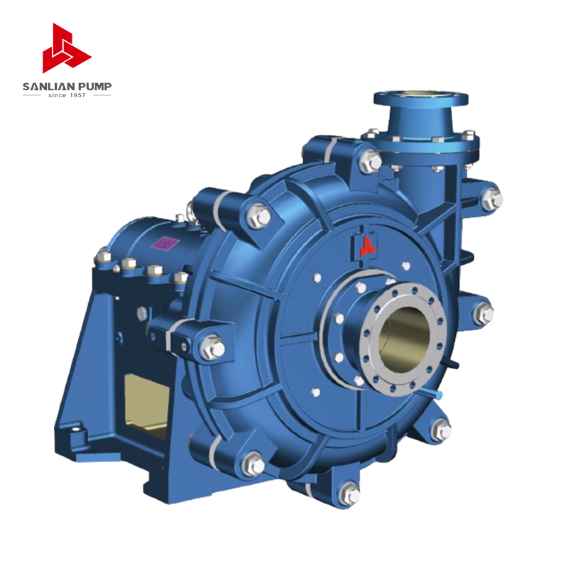
When the pumped fluid contains solids, the efficiency curve changes as surfaces wear. A slurry pump that is designed with thicker vanes and renewable wear parts will keep its initial performance longer than a clean-water pump running in the same duty. Regular inspection of the impeller and casing is necessary; otherwise, the efficiency of pump formula may show a steady decline even though the motor runs at the same speed.
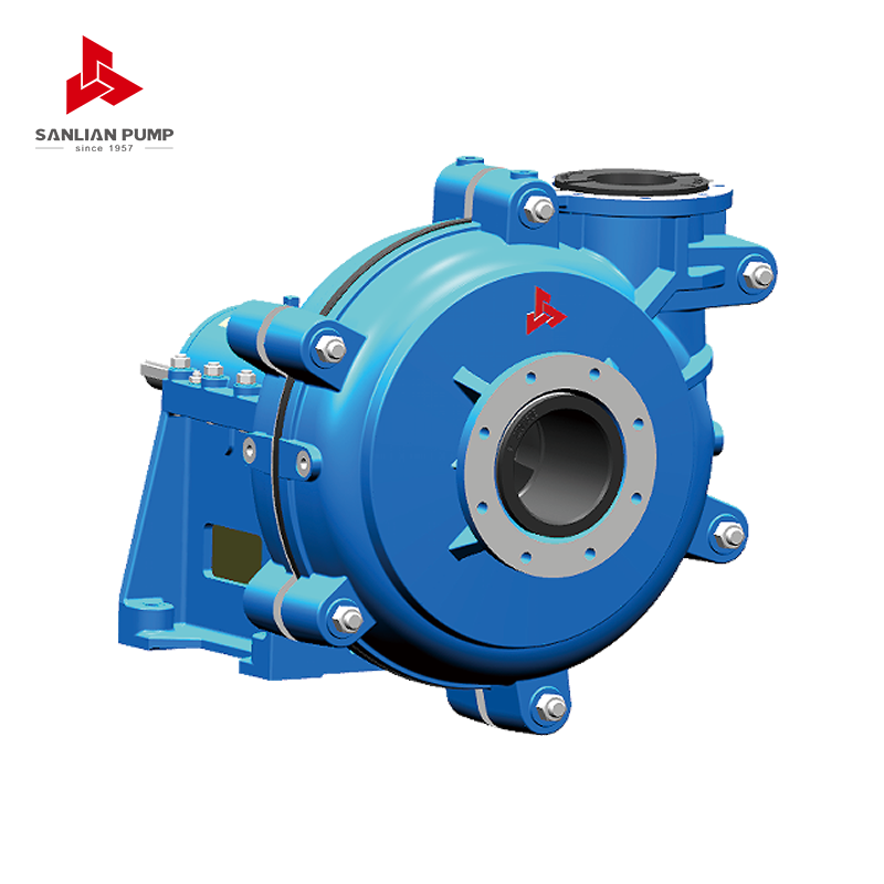 AH Series Horizontal Slurry Pump for Abrasive Solids HandlingDesigned for transporting high-hardness, high-concentration slurries, this cantilever centrifugal pump uses thick vanes and renewable wear parts to sustain performance longer in abrasive conditions, reducing efficiency decline and maintenance frequency.View Product →
Put the Formula to Work in Your Maintenance Plan
The most practical way to use the efficiency of pump formula is to turn it into a trend. Record flow, head, motor power, and speed at regular intervals, then calculate efficiency. If the value drops by 3 to 5 points, schedule an inspection before the problem becomes a failure.
- Measure flow and suction/discharge pressure at the pump flanges.
- Measure motor power from a calibrated meter or a VFD display.
- Calculate hydraulic power and divide by shaft power (or multiply by motor efficiency if using electrical power).
- Compare the result with the pump curve at the current speed and impeller diameter.
- Plan corrective action: trim the impeller, adjust the speed, replace wear rings, or re-line the casing.
For systems with variable demand, a variable-frequency drive is often the lowest-cost way to keep the pump near BEP. For constant flow systems, selecting a pump family that allows easy impeller changes gives the maintenance team the flexibility to restore efficiency after conditions change.
The efficiency of pump formula is not a theory exercise; it is a practical tool for reducing energy cost and protecting equipment life. Start with the basic ratio of hydraulic power to shaft power, convert the units accurately, and then use the result to question how well each pump is matched to its duty. In our work with industrial and municipal systems, the same formula consistently points to the same actions: select close to BEP, monitor the trend, and maintain the internal clearances. Do that, and the pump will return the investment many times over.





 English
 中文简体
中文简体 Français
 Español
 Português
 عربى
عربى


 皖公网安备34052302341647号