The Water Pump at the Centre of Every Fluid System
A water pump is the mechanical heart of any fluid transfer system -- the device that converts rotational energy from a motor into hydraulic energy, moving liquid from one point to another against gravity, friction, and system pressure. From a single building's HVAC circuit to a municipal water distribution network supplying millions of people, the selection of the right water pump type determines whether the system operates efficiently, reliably, and economically over its intended service life -- or whether it suffers from premature wear, energy waste, and maintenance-intensive operation.
Among all water pump configurations used in industrial, commercial, municipal, and infrastructure applications, two centrifugal pump types dominate the majority of installations: the end suction centrifugal pump and the split case pump. These two designs cover a combined flow range from a few cubic metres per hour to more than 6,000 cubic metres per hour, and understanding their operating principles, structural differences, performance characteristics, and optimal application windows is the foundation of competent pump system engineering and procurement.
How Centrifugal Water Pumps Work: The Shared Foundation
Both end suction centrifugal pumps and split case pumps belong to the centrifugal pump family and share the same fundamental operating principle. An electric motor or engine drives a rotating impeller at high speed. The impeller blades impart velocity to the liquid entering the pump, accelerating it radially outward. As the fluid exits the impeller into the volute casing -- a gradually expanding spiral channel -- its velocity is converted into pressure. The pressurised liquid exits through the discharge nozzle and enters the downstream system.
The performance of any centrifugal water pump is described by its pump curve -- a graph plotting head (the pressure the pump generates, measured in metres of liquid column) against flow rate (measured in cubic metres per hour or litres per second). The pump curve intersects the system resistance curve at the operating point. Engineers specify pumps whose operating point falls within plus or minus 10 percent of the Best Efficiency Point (BEP) -- the flow and head combination at which the pump achieves its highest hydraulic efficiency, typically 75 to 90 percent for well-designed centrifugal pumps. Operating significantly below BEP wastes energy; operating above BEP increases cavitation risk and accelerates wear on internal components.
Three parameters govern every pump selection decision regardless of pump type: flow rate (the volume of liquid that must be moved per unit time), total dynamic head (the sum of static head, friction losses in the piping system, and any pressure differential requirements), and Net Positive Suction Head Available (NPSHa) -- the absolute pressure available at the pump inlet above the vapour pressure of the liquid. NPSHa must always exceed the pump's Net Positive Suction Head Required (NPSHr) by a safety margin of at least 0.5 metres to prevent cavitation -- the formation and violent collapse of vapour bubbles that erodes impeller material and causes noise, vibration, and progressive performance loss.
End Suction Centrifugal Pump: Design, Construction, and Operating Principles
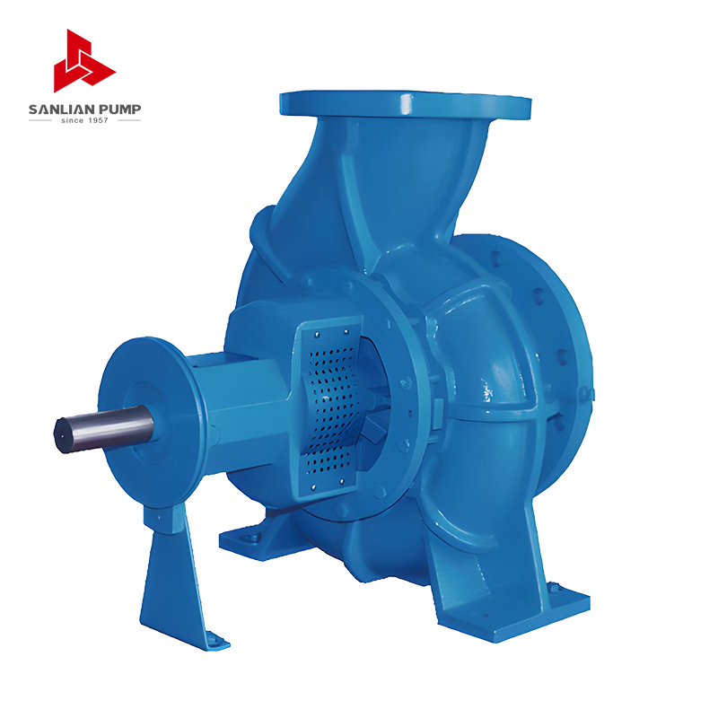
An end suction centrifugal pump is defined by its hydraulic configuration: liquid enters the pump through a suction nozzle positioned at one end of the pump casing, aligned axially with the pump shaft. The fluid travels straight in through the front of the pump, is accelerated by the single-entry impeller, and is discharged through a nozzle oriented at 90 degrees to the suction -- typically vertically upward from the top of the casing, though some configurations discharge to the side or at other angles to suit piping layout requirements.
This axial-inlet, perpendicular-outlet arrangement produces a compact, space-efficient pump that can be installed in confined plant rooms and integrated into complex piping networks with minimal footprint. End suction centrifugal pumps are rotating mechanical devices designed to move fluids by transferring rotational energy from one or more driven rotors called impellers, with the fluid entering through an inlet port aligned with the pump shaft centerline while the discharge is perpendicular to the suction.
Close-Coupled vs. Frame-Mounted Configurations
End suction centrifugal pumps are manufactured in two primary mechanical configurations that determine installation footprint, motor flexibility, and maintenance access:
- Close-coupled configuration: The pump impeller is mounted directly on the motor shaft, eliminating the need for a separate pump shaft, flexible coupling, and bearing frame. The result is a very compact, lightweight assembly with no shaft alignment requirement between pump and motor. Close-coupled end suction pumps are the standard choice for building services, HVAC, irrigation, and other applications where installation simplicity and minimal footprint are priorities. The trade-off is that motor replacement requires removal of the entire pump-motor assembly.
- Frame-mounted (long-coupled) configuration: The pump and motor are separate units, connected by a flexible coupling and mounted on a common baseplate. The pump has its own shaft supported by an independent bearing frame. This configuration provides greater motor flexibility (any compatible motor can be paired with the pump), allows in-situ shaft alignment, and enables the pump unit to be serviced independently of the motor. Frame-mounted end suction pumps are preferred for industrial applications where pump and motor are specified separately, or where the pump handles fluids at elevated temperatures that would damage a close-coupled motor.
Back Pull-Out Design: The Maintenance Advantage
Quality end suction centrifugal pumps feature a back pull-out design -- a construction arrangement that allows the rotating assembly (impeller, mechanical seal, shaft, and bearing frame) to be withdrawn from the rear of the pump casing without disturbing the suction and discharge piping connections or moving the motor. This dramatically reduces maintenance time and cost, as the casing remains bolted in the piping system throughout inspection, seal replacement, or impeller servicing. Back pull-out designs reduce average maintenance time by approximately 40 percent compared to conventional front-access pump designs that require full piping disconnection for internal access.
Performance Range and Operating Limits
The core performance parameters of end suction centrifugal pumps typically include a flow rate range of 5 to 1,000 cubic metres per hour, meeting small to medium flow transfer needs, and a head range of 10 to 200 metres, suitable for low to medium head conditions, with efficiency reaching 75 to 90 percent. These ranges make end suction pumps the most versatile single category of water pump available, capable of serving applications from small domestic booster systems to large industrial process circuits. For fluids other than clean water, material selection becomes critical: end suction centrifugal pumps are suitable for media with viscosity below 200 cSt and solid content not exceeding 5 percent, with material selection matching the corrosiveness of the medium.
Impeller and Casing Material Options
End suction centrifugal pump wetted components are available in a wide range of materials to match the pumped fluid and operating environment. Cast iron is standard for clean water, cooling water, and non-corrosive industrial fluids. Bronze impellers improve corrosion resistance for mildly aggressive media. Stainless steel (grades 304 or 316) is specified for food-grade, pharmaceutical, and mildly corrosive chemical applications. Duplex stainless steel (UNS S32750) handles chlorinated water and seawater at elevated pressures. For highly aggressive acids and alkalis, Hastelloy or titanium alloy impellers extend the pump's chemical compatibility envelope to media that would destroy standard stainless steel components within weeks.
Split Case Pump: Design, Construction, and Operating Principles
A split case pump is a centrifugal pump whose casing is divided into two separate halves along a split plane -- either horizontally (parallel to the shaft axis) or vertically (perpendicular to the shaft). This defining structural feature gives the split case pump its name and its most important practical advantages: access to all internal rotating components without disconnecting the pump from the piping system, and a double-suction impeller configuration that fundamentally changes the pump's hydraulic behaviour compared to a single-suction end suction design.
A split case pump is a centrifugal pump with a casing divided into two parts, designed for high flow rates, stable operation, and easy maintenance. In most industrial and municipal applications, when engineers specify a split case pump they mean a horizontal split case pump -- the configuration where the casing splits along a horizontal plane, with the top half removable by unbolting the casing flange joints, exposing the impeller, shaft, and bearings from above without any pipe movement.
The Double-Suction Impeller: The Performance-Defining Feature
The central engineering distinction of the split case pump is its double-suction impeller -- an impeller design in which liquid enters the rotating element from both sides simultaneously rather than from one end only as in an end suction pump. Unlike a standard impeller that takes in water from one side, a double suction impeller pulls liquid from both sides, balancing the hydraulic thrust and reducing wear on the bearings while allowing the pump to handle much higher flow rates than single-suction designs.
The hydraulic consequences of this double-entry configuration are significant and direct:
- Balanced axial thrust: In a single-suction pump, the pressure differential between the impeller inlet and outlet generates a net axial force on the shaft that must be absorbed by thrust bearings. In a double-suction design, the equal and opposite hydraulic forces from both sides of the impeller cancel each other, effectively eliminating net axial thrust. This dramatically reduces bearing load and heat generation, extending bearing life and allowing the pump to be built with a between-bearings shaft arrangement where the impeller sits midway between two bearing supports -- far more structurally stable than the overhung shaft arrangement of most end suction pumps.
- Lower NPSH required: Because the total flow is split equally between two impeller inlets, the velocity at each inlet eye is approximately half that of a single-suction impeller handling the same total flow. Lower inlet velocity means lower dynamic pressure drop at the inlet, which means the pump requires less absolute suction pressure to avoid cavitation. Low NPSH values minimise cavitation risk, enabling safe operation at high speeds, and making split case pumps well-suited to applications where suction conditions are marginal or where the pump must operate at variable speed.
- Very high flow capacity: The double-entry design allows split case pumps to handle total flow rates that would require impeller diameters too large for practical end suction construction. Horizontal and vertical split case centrifugal pumps provide great performance metrics with pump capacity as high as 6,000 cubic metres per hour and a maximum pressure head of 200 metres. This flow ceiling -- far exceeding anything achievable with a standard end suction configuration -- makes split case pumps the only viable centrifugal pump solution for large municipal water supply systems, major fire protection installations, and high-volume industrial cooling circuits.
Horizontal vs. Vertical Split Case Configurations
Split case pumps are built in two casing orientations that suit different installation environments:
- Horizontal split case (HSC): The most widely installed configuration. The casing splits along a horizontal plane through the shaft centreline. The top half is removable for full internal access. Suction and discharge nozzles are both located in the bottom casing half, meaning the piping connections remain undisturbed during maintenance. HSC pumps are installed on a rigid concrete or steel baseplate and require adequate headroom above the pump for top-casing removal. They are the standard for municipal water supply, large HVAC primary circuits, fire pump installations, irrigation mainlines, and industrial cooling water systems.
- Vertical split case (VSC): The casing splits along a vertical plane perpendicular to the shaft. The shaft is vertical and the pump occupies a smaller floor footprint than an equivalent HSC unit, making it suitable for installations with limited floor space but adequate height clearance. VSC pumps are used in high-rise building booster systems, offshore platforms, and process plant installations where plan area is constrained.
The Maintenance Advantage of the Split Casing
In traditional end-suction pumps, accessing the impeller often requires dismantling pipes and moving heavy motors. With a split case pump, technicians can lift the top casing to inspect or replace worn parts in a fraction of the time -- a feature that is crucial for facilities that cannot afford prolonged shutdowns. This maintenance accessibility is not merely a convenience in large pump installations -- it is a genuine operational cost factor. With proper maintenance, 20 to 30 years of service life is common in water applications for split case pumps, a service life that reflects both the robustness of the between-bearings design and the ability to inspect and replace wear components without the collateral disruption that end suction pump maintenance requires at large scale.
End Suction vs. Split Case Pump: Direct Comparison
| Parameter |
End Suction Centrifugal Pump |
Split Case Pump |
| Suction configuration |
Single suction, axial inlet one side |
Double suction, inlet from both sides |
| Typical flow range |
5 to 1,000 cubic metres per hour |
200 to 6,000 cubic metres per hour |
| Typical head range |
10 to 200 metres |
10 to 200 metres |
| Axial thrust |
High -- absorbed by thrust bearing |
Near zero -- self-balancing design |
| Shaft arrangement |
Overhung (impeller cantilevered from bearing) |
Between-bearings (impeller supported both sides) |
| Peak hydraulic efficiency |
75 to 88 percent |
88 to 93 percent |
| NPSHr at equivalent flow |
Higher |
Lower (split flow to two inlets) |
| Installation footprint |
Compact -- small floor area |
Larger -- requires more floor and head room |
| Maintenance access |
Back pull-out (piping stays); moderate downtime |
Top casing removal (piping stays); rapid access |
| Bearing life |
Good -- reduced by axial thrust load |
Very long -- minimal axial thrust load |
| Initial capital cost |
Lower |
Higher |
| Typical service life |
10 to 20 years |
20 to 30 years |
| Relevant standards |
ISO 2858, EN 733, ASME B73.1 |
ISO 9906, NFPA 20, Hydraulic Institute |
Table 1: Direct comparison of end suction centrifugal pumps and split case pumps across key design, performance, and operational parameters.
Industrial and Municipal Applications by Pump Type
| Application Sector |
Preferred Pump Type |
Governing Selection Reason |
| HVAC building services (secondary circuit) |
End Suction Centrifugal |
Compact, low-medium flow, close-coupled simplicity |
| HVAC primary plant (chiller primary loop) |
Split Case |
High flow, continuous duty, efficiency requirement |
| Municipal water supply (district level) |
Split Case |
Very high flow, 24/7 operation, long service life |
| Municipal water supply (building booster) |
End Suction Centrifugal |
Moderate flow, compact plant room, lower cost |
| Fire protection (NFPA 20 listed systems) |
Split Case (preferred) or End Suction |
Reliability, high flow demand, NFPA listing |
| Industrial process cooling |
Split Case |
High flow, balanced thrust, low maintenance downtime |
| Agricultural and landscape irrigation |
End Suction Centrifugal |
Medium flow, seasonal use, cost sensitivity |
| Large-scale agricultural irrigation mainline |
Split Case |
Very high flow, remote site efficiency requirement |
| Power plant cooling water |
Split Case |
Massive flow volumes, continuous operation, efficiency |
| Chemical process (corrosive fluids) |
End Suction Centrifugal (ASME B73.1) |
Chemical-grade construction, dimensional standard |
| Mining dewatering and process water |
Split Case |
High flow, robust construction for harsh environments |
| Marine shipboard systems |
Both types depending on flow requirement |
Compact for auxiliary; split case for main cooling |
Table 2: Application sector mapping for end suction centrifugal pumps and split case pumps, with governing reason for pump type selection in each sector.
Water Pump Standards and Certifications: What They Mean for Buyers
Both end suction centrifugal pumps and split case pumps are subject to international dimensional, performance, and quality standards that govern interchangeability, testing, and fitness for specific applications. Understanding which standards apply to your procurement context prevents mismatched specifications and ensures that replacement parts and second-source pump units will be dimensionally compatible with existing installations.
- ISO 2858 and EN 733: The two most widely adopted international dimensional standards for end suction centrifugal pumps. ISO 2858 governs end-suction single-stage pumps for chemical and process applications. EN 733 (formerly DIN 24255) covers standard water pump end suction designs. Both standards define flange dimensions, shaft heights, and baseplate layouts to ensure interchangeability between pumps from different manufacturers of the same nominal size. Specifying EN 733 or ISO 2858 compliance in a procurement contract is the most effective way to protect against vendor lock-in on replacement units.
- ASME B73.1: The American Society of Mechanical Engineers standard for horizontal end suction centrifugal pumps for chemical process service. This standard covers metallic and solid polymer centrifugal pumps of horizontal, end suction single stage, centerline discharge design, and includes dimensional interchangeability requirements and certain design features to facilitate installation and maintenance and to enhance reliability and safety. ASME B73.1 pumps from any compliant manufacturer are dimensionally interchangeable, making them the dominant specification in US chemical plant procurement.
- NFPA 20: The National Fire Protection Association standard for fire pump installations. Split case pumps are explicitly listed in NFPA 20 as an approved fire pump configuration, and NFPA 20-listed split case pumps must pass a full factory performance acceptance test to the published pump curve. The between-bearings design and double-suction reliability of the split case configuration make it the preferred fire pump type in large commercial, industrial, and infrastructure fire protection systems.
- ISO 9906: The international standard for hydraulic performance testing of rotodynamic pumps. ISO 9906 defines acceptance test grades (Grade 1, Grade 2, Grade 3) with progressively tighter tolerances on flow, head, power, and efficiency. Grade 1 tolerances (plus or minus 2.5 percent on flow and head) are required for precision installations; Grade 2 tolerances (plus or minus 4.5 percent) are standard for most industrial and municipal pump procurement.
- IE efficiency class (motor): While not a pump standard, the International Electrotechnical Commission motor efficiency classification (IE3 Premium Efficiency minimum; IE4 Super Premium for new large installations in the EU) directly affects total system energy cost. Energy cost accounts for approximately 80 percent of a pump system's total lifecycle cost over a 10-year operating period -- far exceeding capital equipment and maintenance costs combined -- making motor efficiency class a procurement decision that merits detailed whole-life cost analysis rather than default selection.
Cavitation: The Most Common Cause of Water Pump Failure
Cavitation is the single most destructive operating condition for any centrifugal water pump, and it is more common than most operators realise. It occurs when the absolute pressure at the pump inlet falls below the vapour pressure of the liquid being pumped -- at that point, microscopic vapour bubbles form in the low-pressure zone at the impeller inlet. As these bubbles travel into the higher-pressure region further into the impeller, they collapse violently, generating localised pressure spikes that pit and erode metal surfaces. Sustained cavitation produces a characteristic crackling or gravel-like noise from the pump, progressive impeller damage visible as cratering of the blade leading edges, loss of flow and pressure performance, and eventually catastrophic impeller failure.
Preventing cavitation requires ensuring that the NPSHa at the pump inlet exceeds the pump manufacturer's stated NPSHr at the operating flow rate by a safety margin of at least 0.5 metres for clean cold water and larger margins for hot water or volatile liquids. The following installation factors reduce NPSHa and must be accounted for in the system design:
- Pump installation height above the suction source: Every metre of elevation between the suction source and the pump inlet reduces NPSHa by one metre. Pumps should be installed as close to and as low as practical relative to the suction source.
- Suction pipe friction losses: Long suction runs, small suction pipe diameters, and high flow velocities all increase friction pressure drop on the suction side, reducing NPSHa. Suction piping should be one size larger than the pump suction nozzle, and elbows immediately before the pump inlet should be avoided -- use at least 5 to 10 pipe diameters of straight pipe before the inlet.
- Liquid temperature: Hot water has a higher vapour pressure than cold water, meaning less absolute pressure is available to suppress cavitation at the same installation conditions. A pump that operates safely on cold water may cavitate on hot condensate at 80 degrees Celsius from the same suction arrangement.
- Operating above rated flow: Pump NPSHr increases steeply as flow increases above the BEP flow rate. A pump operating at 120 percent of its rated flow may require significantly more NPSHa than its nameplate NPSHr value suggests, as that value is typically stated at BEP conditions.
Mechanical Seals, Packing, and Sealing Technology for Water Pumps
The shaft seal is the component where the rotating pump shaft passes through the stationary pump casing. It prevents process fluid from escaping to atmosphere and prevents air ingress on the suction side. Two technologies dominate water pump shaft sealing:
Mechanical seals are the standard in modern end suction centrifugal pumps and split case pumps for clean water and most industrial applications. A mechanical seal consists of two flat, precision-lapped sealing faces -- one rotating with the shaft, one stationary in the casing -- held in contact by a spring. The faces are typically carbon-graphite against silicon carbide, or silicon carbide against silicon carbide for abrasive applications. Mechanical seals are virtually leak-free in normal operation, require no periodic adjustment, and have a service life of 2 to 5 years in clean water service before replacement is required. They do not tolerate dry running -- even momentary loss of liquid at the seal faces generates heat that destroys the lapped surfaces within seconds.
Gland packing (compressed packing rings around the shaft in a stuffing box) is an older technology that allows a controlled, intentional small leakage of water -- typically 20 to 60 drops per minute -- which lubricates and cools the packing. Gland packing is specified where mechanical seals are impractical (very large shaft diameters, abrasive slurry service, or legacy pump designs without mechanical seal space). It requires periodic adjustment as the packing wears and compresses, and periodic replacement when the stuffing box can no longer hold an adequate seal. In clean water applications, mechanical seals are preferred because they eliminate the continuous water loss and labour of packing management.
Variable Speed Drives and Energy Optimisation for Water Pumps
In systems where the required flow rate or head varies over time -- building water supply with fluctuating demand, HVAC circuits with variable occupancy loads, irrigation systems with different zone requirements -- running a fixed-speed pump at its rated speed continuously wastes energy whenever the system demand is below the pump's design point. A pump running at 80 percent of its rated speed delivers only 51 percent of the power consumption of the same pump at full speed, following the affinity law relationship where power varies with the cube of speed. Variable frequency drives (VFDs) that modulate pump speed to match actual system demand are the single most effective energy conservation measure available for water pump systems.
End suction centrifugal pumps and split case pumps are both fully compatible with VFD speed control. For end suction pumps in building HVAC and water supply applications, VFD control is essentially standard practice in new installations governed by modern building energy codes. For large split case pumps in municipal and industrial service, VFD control requires careful hydraulic analysis to ensure the pump remains in a stable operating region across the full speed range -- split case pumps can experience instability near shut-off head at reduced speed, and the minimum continuous stable flow requirement must be respected at all operating conditions.
Pump Selection Framework: Choosing Between End Suction and Split Case
The decision between an end suction centrifugal pump and a split case pump for a given application is governed by a structured set of criteria. Working through these questions in sequence produces a defensible pump type selection:
- What is the required flow rate? If the design flow exceeds approximately 500 to 700 cubic metres per hour, a split case pump is almost certainly the better choice. Below this threshold, both types are viable and other criteria determine the selection. Above this threshold, the end suction configuration becomes mechanically stressed and less efficient, while the split case double-suction design handles high flow naturally and with better NPSH characteristics.
- Is continuous or critical-duty operation required? If the pump must run 24 hours per day, 7 days per week with minimal planned downtime -- as in municipal water supply, hospital water systems, or fire pump duty -- the split case pump's longer service life, balanced bearing loads, and rapid maintenance access make it the more appropriate specification. End suction pumps are entirely suitable for continuous duty at moderate flow rates but require longer maintenance interventions when internal components need servicing.
- What is the available floor space and headroom? If the plant room or pump station has very limited floor area or ceiling height, the end suction centrifugal pump's smaller footprint and lower profile give it a clear installation advantage. Split case pumps require adequate floor area for the pump-motor set plus maintenance access space around the perimeter, and headroom above the pump for top-casing removal during service.
- What are the suction conditions? If NPSHa is marginal -- because the pump must draw from a low-level tank, a long suction run, or a hot water source -- the split case pump's lower NPSHr at equivalent flow gives it a meaningful advantage in avoiding cavitation. Where NPSHa is generous, this factor does not differentiate the two types.
- What is the whole-life cost budget? End suction centrifugal pumps have a lower initial capital cost than split case pumps of equivalent duty. However, split case pumps' longer service life, lower energy consumption at high flow rates, and lower cost per maintenance event typically result in lower total lifecycle cost for large-flow, long-duration applications. For small-flow, shorter-service-life applications, the end suction pump's lower capital cost usually wins on lifecycle economics.
- Is a specific regulatory or application standard mandatory? For chemical process applications in the USA, ASME B73.1 end suction pump compliance may be mandatory. For NFPA 20-listed fire pump installations above certain flow thresholds, a listed split case pump configuration is typically required. Regulatory compliance requirements must be determined before finalising pump type selection, as they may override purely hydraulic or economic optimisation.
Commissioning, Installation, and First-Year Maintenance Priorities
The majority of premature water pump failures occur within the first year of operation and are attributable to installation errors rather than manufacturing defects. The following commissioning priorities apply to both end suction centrifugal pumps and split case pumps and represent the most effective investment in long-term pump reliability:
- Foundation and baseplate grouting: The foundation must be rigid, level, and properly grouted; weak foundations cause vibration, misalignment, and premature bearing failure. Baseplate flatness must be checked before setting the pump, shimming as necessary to eliminate rocking or gaps, and grouting thoroughly to create a solid, vibration-free mounting.
- Shaft alignment verification: Coupling alignment between pump and motor must be verified with dial indicators after grouting and piping connection -- piping stress applied to the pump casing causes casing distortion that shifts shaft alignment from the pre-piping condition. Angular and parallel misalignment exceeding 0.05 millimetres is the leading cause of mechanical seal failure and bearing overheating in the first year of operation.
- Rotation check before first start: Always verify impeller rotation direction before filling the pump and starting under load. Incorrect rotation (motor connected with wrong phase sequence) delivers approximately 60 percent of rated head with substantially higher noise and vibration -- conditions that damage mechanical seals and bearings within minutes.
- Controlled start-up: Cold start requires gradually ramping to full speed over 30 seconds to avoid water hammer, keeping pressure spikes to no more than 1.25 times the rated pressure. For split case pumps handling large volumes, the valve opening sequence must be coordinated with pump start to prevent reverse flow through parallel pump units.
- Vibration baseline measurement: Record vibration velocity measurements at each bearing housing in three axes within the first week of commissioned operation. This baseline is the reference against which all future condition monitoring measurements are compared -- early detection of developing bearing defects, impeller imbalance, or cavitation through trending vibration against this baseline is far more reliable than threshold-based alarm monitoring alone.


 English
 中文简体
中文简体 Français
 Español
 Português
 عربى
عربى


 皖公网安备34052302341647号