What Is a Non Self-Priming Vertical Multistage Centrifugal Pump?
A non self-priming vertical multistage centrifugal pump is a specialized fluid-handling device designed to move water or other compatible liquids through a series of impeller stages arranged vertically. Unlike self-priming pumps, this type requires the pump casing and inlet pipework to be fully filled with liquid before startup. The "multistage" aspect means that the fluid passes through multiple impellers in sequence, with each stage adding energy and progressively increasing the pressure. This configuration allows the pump to achieve high head values that a single-stage pump simply cannot reach.
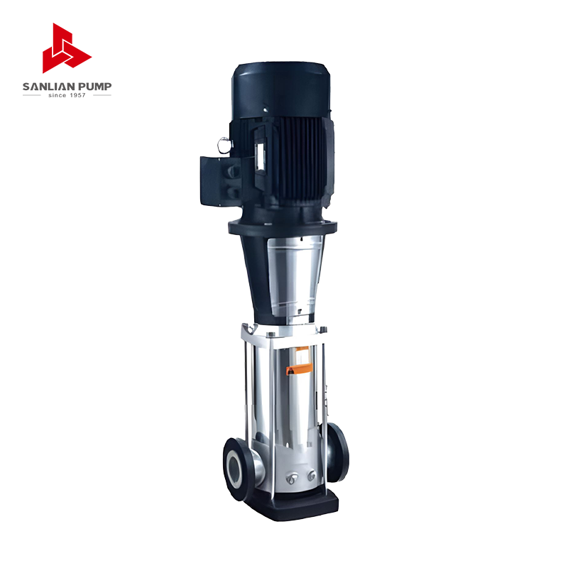
The vertical orientation of these pumps is not accidental—it serves a functional purpose. By aligning the stages vertically, the pump occupies a minimal footprint, making it highly suitable for installations where floor space is limited. The motor sits directly above the pump body, connected via a rigid shaft, eliminating the need for complex coupling arrangements. This compact and efficient design is widely favored in municipal water supply systems, industrial pressure boosting, irrigation, and high-rise building water distribution.
How the Multistage Design Builds Pressure
The core engineering principle behind a multistage centrifugal pump is the sequential energy addition to the fluid. When liquid enters the first stage impeller, it is accelerated outward by centrifugal force, converting kinetic energy into pressure as it passes through a diffuser or volute. Instead of being discharged at this point, the pressurized liquid is channeled directly into the inlet of the second impeller, where the process repeats. Each stage typically adds an equal increment of pressure, so a pump with five stages can deliver five times the head of a comparable single-stage unit operating under the same conditions.
This makes multistage pumps exceptionally efficient for applications requiring high differential pressure but relatively moderate flow rates. The vertical shaft design also ensures that all impellers are balanced on the same centerline, reducing radial thrust and minimizing vibration. Proper hydraulic balancing between stages is critical, and manufacturers achieve this through precision-machined wear rings and carefully matched impeller geometries. The end result is a pump that delivers consistent, stable performance over a wide operating range.
Why "Non Self-Priming" Matters for Installation
The term "non self-priming" is one of the most practically significant characteristics of this pump type. A self-priming pump can evacuate air from its suction line and casing independently before pumping begins. A non self-priming pump cannot do this—it relies entirely on gravity feed, flooded suction, or external priming equipment to ensure the impellers are submerged in liquid at startup. If the pump is started dry or with air in the casing, the impellers will spin without generating any meaningful pressure, and the pump may suffer rapid mechanical damage due to dry running.
This requirement directly influences how and where the pump can be installed. Non self-priming vertical multistage centrifugal pumps are best suited for:
- Installations where the water source is above the pump inlet (flooded suction conditions)
- Systems connected directly to a pressurized water main or storage tank
- Setups equipped with a foot valve and separate priming line
- Applications where the pump is always submerged or gravity-fed from an elevated reservoir
When these conditions are met, the non self-priming design is not a limitation but simply a design choice that allows for a simpler, more compact, and more hydraulically efficient pump body. Engineers who understand this distinction can plan installations that exploit the pump's strengths while avoiding dry-run scenarios through the use of pressure switches, level sensors, and check valves.
Key Components and Construction Materials
Understanding the internal components of a non self-priming vertical multistage centrifugal pump helps users make better maintenance and material selection decisions. The main components include:
Impellers
Impellers are the rotating elements responsible for energy transfer. In most vertical multistage designs, closed impellers are used because they offer higher efficiency and are better at controlling internal recirculation. They are typically manufactured from stainless steel (AISI 304 or 316), cast iron, or engineering plastics depending on the fluid compatibility requirements.
Pump Casing and Stage Chambers
The stage chambers guide the fluid between impellers and house the diffusers that convert velocity into pressure. Stainless steel is the most common material due to its corrosion resistance, cleanability, and suitability for potable water applications. Cast iron casings are used in industrial applications where cost is prioritized over corrosion resistance.
Shaft and Bearings
The central shaft transmits torque from the motor to all impellers simultaneously. It must be precisely machined to minimize runout and balanced to prevent vibration. Radial and thrust bearings support the shaft, with the thrust bearing in particular managing the axial forces generated by multistage hydraulic loading.
Mechanical Seal
The mechanical seal prevents fluid from leaking along the shaft where it exits the pump casing. In vertical multistage designs, the seal is typically located at the top of the pump stack, close to the motor. Carbon/ceramic face combinations are standard for clean water, while silicon carbide faces are used for slightly abrasive or chemically aggressive fluids.
Typical Applications Across Industries
Non self-priming vertical multistage centrifugal pumps are found across a surprisingly wide range of sectors. Their ability to generate high head in a small footprint makes them the default choice in many demanding installations. The table below summarizes common applications and the relevant performance requirements:
| Industry / Application |
Typical Use |
Key Requirement |
| Municipal Water Supply |
Pressure boosting in distribution networks |
High head, continuous duty, potable compliance |
| Commercial Buildings |
Domestic water pressure in high-rise towers |
Quiet operation, compact footprint, reliability |
| Industrial Process |
Cooling water circuits, boiler feed |
Temperature resistance, material compatibility |
| Agriculture / Irrigation |
Drip and sprinkler system pressurization |
Energy efficiency, variable flow handling |
| Fire Fighting Systems |
Jockey and main pressure maintenance pumps |
Instant response, high reliability |
Selecting the Right Pump: Key Parameters to Evaluate
Choosing the correct non self-priming vertical multistage centrifugal pump requires a careful assessment of your system's hydraulic demands. Undersizing leads to inadequate pressure and flow, while oversizing wastes energy and causes premature wear. The following parameters must be defined before selection:
- Required Flow Rate (Q): Expressed in liters per minute (L/min) or cubic meters per hour (m³/h), this determines the hydraulic size of the pump and influences impeller diameter.
- Total Dynamic Head (TDH): This is the total pressure the pump must overcome, including static elevation, friction losses in pipes, and any back pressure from the system. It is expressed in meters (m) of water column.
- Number of Stages: Once the per-stage head capability is known from the pump curve, dividing TDH by per-stage head gives the required number of stages. Manufacturers typically offer the same pump body with variable stage counts.
- Net Positive Suction Head Available (NPSHa): This must exceed the pump's NPSHr (required) by a safe margin—typically at least 0.5 m—to prevent cavitation, which causes noise, vibration, and impeller erosion.
- Fluid Temperature and Viscosity: Standard pumps are rated for water up to 40°C. Higher temperatures or viscous fluids require derating of performance and careful material selection.
- Motor Power and Efficiency Class: Always verify that the selected motor power covers the maximum power point on the pump curve, not just the duty point. IE3 or IE4 efficiency motors reduce operating costs significantly in continuous-duty applications.
Installation Best Practices
Correct installation is essential for achieving the rated performance and service life of a non self-priming vertical multistage centrifugal pump. Since these units cannot prime themselves, the suction conditions must be carefully managed. Always install a strainer on the suction line to prevent debris from entering the impellers—particulates as small as 1 mm can cause wear ring damage over time. A foot valve or suction check valve should be used if the water source is below the pump, combined with a priming valve or filling port to flood the casing before startup.
Suction pipework should be as short and straight as possible, with a diameter equal to or larger than the pump inlet flange. Avoid reducing the suction pipe diameter, as this increases velocity and reduces NPSHa. On the discharge side, install an isolating valve and a non-return check valve to prevent backflow when the pump stops. Flexible connectors on both suction and discharge ports help isolate vibration from the building structure. Always mount the pump on a rigid, level base—vertical multistage pumps are sensitive to misalignment and will develop bearing and seal failures if the baseplate is not properly supported.
Maintenance Schedule and Common Fault Diagnosis
Routine maintenance of a vertical multistage centrifugal pump is relatively straightforward compared to horizontal split-case designs, because all wear components are accessible from the top without disturbing the pipework. A typical maintenance schedule includes checking the mechanical seal for leakage every three months, inspecting motor bearings every six months, and performing a full hydraulic performance test annually to detect wear ring deterioration. When flow rate drops noticeably without a change in system resistance, worn wear rings are almost always the cause.
Common faults and their likely causes include:
- No flow or low pressure at startup: Air in the casing due to insufficient priming; check suction line, foot valve, and casing vent.
- Cavitation noise (crackling or rattling): NPSHa is too low; check suction pipe restrictions, fluid temperature, or reduce pump speed.
- Excessive vibration: Impeller imbalance due to wear, bearing failure, or pipe-induced mechanical stress; inspect bearings and check pipe supports.
- Mechanical seal leakage: Seal face wear or incorrect installation; replace seal faces and verify correct spring compression during reassembly.
- Motor overheating: Pump operating far from best efficiency point, low voltage supply, or blocked motor cooling fins; verify duty point and electrical supply quality.
By keeping a maintenance log and trending performance data over time, operators can identify gradual degradation early and plan predictive replacements rather than reactive repairs. Non self-priming vertical multistage centrifugal pumps are robust and long-lived machines when operated within their designed parameters and maintained on a consistent schedule.


 English
 中文简体
中文简体 Français
 Español
 Português
 عربى
عربى

 皖公网安备34052302341647号